|
|
||
|---|---|---|
| .. | ||
| Readme.md | ||
| SpeedyBeeF405WING.png | ||
| SpeedyBeeF405WING_wiring.png | ||
| defaults.parm | ||
| hwdef-bl.dat | ||
| hwdef.dat | ||
Readme.md
SpeedyBeeF405WING Flight Controller
The SpeedyBeeF405WING is a flight controller produced by SpeedyBee.
Features
Processor
    STM32F405 168Mhz, 1MB 32-bit processor
    AT7456E OSD
Sensors
    ICM42688P Acc/Gyro
    SPL006 barometer
Power
    2S - 6S Lipo input voltage with voltage monitoring
    90A Cont., 215A peak current monitor
    9V/12/5V, 1.8A BEC for powering Video Transmitter controlled by GPIO
    4.9V/6V/7.2V, 4.5A BEC for servos
    5V, 2.4A BEC for internal and peripherals
Interfaces
    12x PWM outputs DShot capable (Serail LED output is PWM12)
    1x RC input
    5x UARTs/serial for GPS and other peripherals, 6th UART internally tied to Wireless board)
    I2C port for external compass, airspeed, etc.
    microSDCard for logging, etc.
    USB-C port
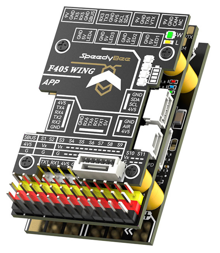
Pinout
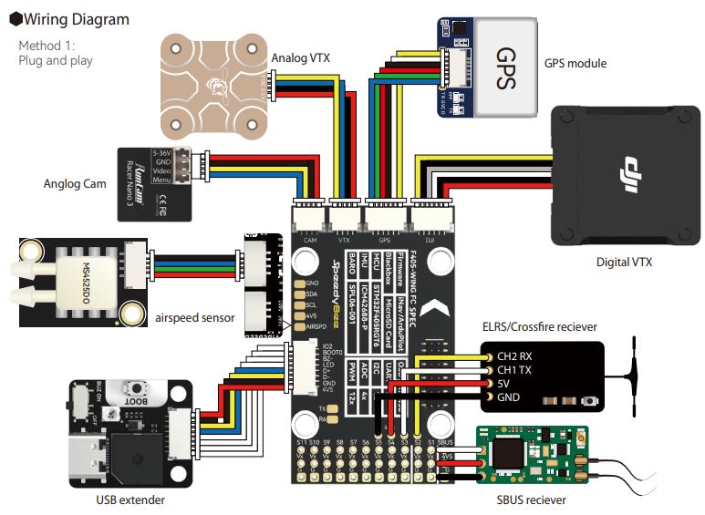
Wiring Diagram
UART Mapping
The UARTs are marked Rn and Tn in the above pinouts. The Rn pin is the receive pin for UARTn. The Tn pin is the transmit pin for UARTn.
- SERIAL0 -> USB
- SERIAL1 -> USART1 (Serial RC input) (DMA capable)
- SERIAL2 -> USART2 (RX tied to inverted SBUS RC input, but can be used as normal UART if :ref:
BRD_ALT_CONFIG<>=1) - SERIAL3 -> UART3 (GPS) (TX DMA capable)
- SERIAL4 -> UART4 (User) (TX DMA capable)
- SERIAL5 -> UART5 (User, available on DJI air unit connector) (TX DMA capable)
- SERIAL6 -> UART6 (tied to internal wireless module, MAVLink2 telem)
RC Input
RC input is configured on the SBUS pin (inverted and sent to UART2_RX). It supports all RC protocols except serial protocols such as CRSF, ELRS, etc. Those devices can be connected to USART1 TX and RX, instead. Fport can be connected to USART1 TX also, but will require an external bi-directional inverter and the ref:`SERIAL1_OPTION<SERIAL1_OPTION>' = 4 (HalfDuplex) set.
OSD Support
The SpeedyBeeF405Wing supports using its internal OSD using OSD_TYPE 1 (MAX7456 driver). External OSD support such as DJI or DisplayPort is supported using UART5 or any other free UART5. See :ref:common-msp-osd-overview-4.2 for more info.
PWM Output
The SpeedyBeeF405Wing supports up to 12 PWM outputs (PWM12 is the serial LED output, by default). All outputs support DShot.
The PWM is in 5 groups:
- PWM 1,2 in group1
- PWM 2,4 in group2
- PWM 5-7 in group3
- PWM 8-10 in group4
- PWM 11,12 in group5 Note: PWM12 is setup for LED use by default, if PWM11 is used, you must re-assign PMW12 to a normal PWM output or nothing
Channels within the same group need to use the same output rate. If any channel in a group uses DShot then all channels in that group would need to use DShot.
Battery Monitoring
The board has a builting voltage and current sensor. The current sensor can read up to 90A continuosly, 215 Amps peak. The voltage sensor can handle up to 6S LiPo batteries.
The correct battery setting parameters are set by default and are:
- BATT_MONITOR 4
- BATT_VOLT_PIN 10
- BATT_CURR_PIN 11
- BATT_VOLT_MULT 11.5
- BATT_AMP_PERVLT 50
Compass
The SpeedyBeeF405Wing does not have a built-in compass, but you can attach an external compass using I2C on the SDA and SCL pads.
VTX power control
GPIO 81 controls the VTX BEC output to pins marked "9V". Setting this GPIO high removes voltage supply to pins.
Loading Firmware
Firmware for these boards can be found at https://firmware.ardupilot.org in sub-folders labeled “SpeedyBeeF405Wing”.
Initial firmware load can be done with DFU by plugging in USB with the boot button pressed. Then you should load the "SpeedyBeeF405Wing_bl.hex" firmware, using your favourite DFU loading tool.
Subsequently, you can update firmware with Mission Planner.