setting up a DEFAULTGPIO pulldown in bootloaders is a bad idea as it overrides any hardware pullups that have been put in place as part of a "hold in bootloader" mechanism. See discussion in #27360 for ELRS note that this only impacts one board that I can see, the BlitzF745AIO, due to the MCU vs DEFAULTGPIO interaction |
||
|---|---|---|
| .. | ||
| README.md | ||
| hwdef-bl.dat | ||
| hwdef.dat | ||
| main.png | ||
| pinmap_bottom.png | ||
| pinmap_top.png | ||
README.md
ThePeach FCC-K1
:::warning Ardupilot does not manufacture this (or any) autopilot. Contact the manufacturer for hardware support or compliance issues. :::
ThePeach FCC-K1 is an advanced autopilot designed and manufactured in ThePeach.
Specifications
-
Main Processor: STM32F427VIT6
- 32bit ARM Cortex-M4, 168 MHz 256 KB RAM 2 MB Flash memory
-
IO Processor: STM32F100C8T6
- ARM Cortex-M3, 32bit ARM Cortex-M3, 24 MHz, 8KB SRAM
-
On-board sensors
- Accel/Gyro: ICM-20602
- Accel/Gyro/Mag: MPU-9250
- Barometer: MS5611
-
Interfaces
- 8+5 PWM output (8 from IO, 5 from FMU)
- Spektrum DSM / DSM2 / DSM-X Satellite compatible input
- Futaba S.BUS compatible input and output
- PPM sum signal input
- Analogue / PWM RSSI input
- S.Bus servo output
- Safety switch/LED
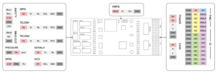
- 4x UART Ports: TELEM1, TELEM2, GPS, SERIAL4
- 2x I2C Ports
- 1x CAN bus
- 1x ADC
- Analog inputs for voltage / Current of 1 battery
-
Mechanical
- Dimensions: 40.2 x 61.1 x 24.8 mm
- Weight: 65g
Connectors
Serial Port Mapping
| UART | Device | Port |
|---|---|---|
| USART1 | /dev/ttyS0 | IO Processor Debug |
| USART2 | /dev/ttyS1 | TELEM1 (flow control) |
| USART3 | /dev/ttyS2 | TELEM2 (flow control) |
| UART4 | /dev/ttyS3 | GPS1 |
| USART6 | /dev/ttyS4 | PX4IO |
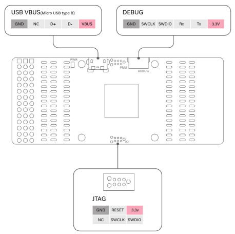
| UART7 | /dev/ttyS5 | Debug Console |
| UART8 | /dev/ttyS6 | TELEM4 |
Voltage Ratings
ThePeach FCC-K1 can be double-redundant on the power supply if two power sources are supplied. The two power rails are: POWER and USB.
:::note The output power rails FMU PWM OUT and I/O PWM OUT do not power the flight controller board (and are not powered by it). You must supply power to one of POWER or USB or the board will be unpowered. :::
Normal Operation Maximum Ratings
Under these conditions all power sources will be used in this order to power the system:
- POWER input (5V to 5.5V)
- USB input (4.75V to 5.25V)
Absolute Maximum Ratings
Under these conditions, all power sources cause permanent damage to the flight controller.
- POWER input (5.5V Over)
- USB input (5.5V Over)
Where to buy
Order from ThePeach


