| .. | ||
| fc-dk-preliminary-datasheet.png | ||
| fc-overlay-top-144-dpi.jpg | ||
| flight_core_v1_imu_locations.png | ||
| flight-core-dims.png | ||
| flight-core.jpg | ||
| hwdef-bl.dat | ||
| hwdef.dat | ||
| README.md | ||
ModalAI Flight Core v1 Controller
The ModalAI FlightCore is a flight controller made in the USA. The Flight Core can be paired with ModalAI VOXL for obstacle avoidance and GPS-denied navigation, or used independently as a standalone flight controller.
Buy Here
See Flight Core Documentation Here
See Flight Core Datasheet Here
Features
| Feature | Details |
|---|---|
| Weight | 6 g |
| MCU | 216MHz, 32-bit ARM M7 STM32F765II |
| Memory | 256Kb FRAM |
| 2Mbit Flash | |
| 512Kbit SRAM | |
| IMUs | ICM-20602 (SPI1) |
| ICM-42688-P (SPI2) | |
| BMI088 (SPI6) | |
| Barometer | BMP388 (I2C4) |
| Secure Element | A71CH (I2C4) |
| microSD Card | Information on supported cards |
| Inputs | GPS/Mag |
| Spektrum | |
| Telemetry | |
| CAN bus | |
| PPM | |
| Outputs | 6 LEDs (2xRGB) |
| 8 PWM Channels | |
| Extra Interfaces | 3 serial ports |
| I2C | |
| GPIO |
Pinout
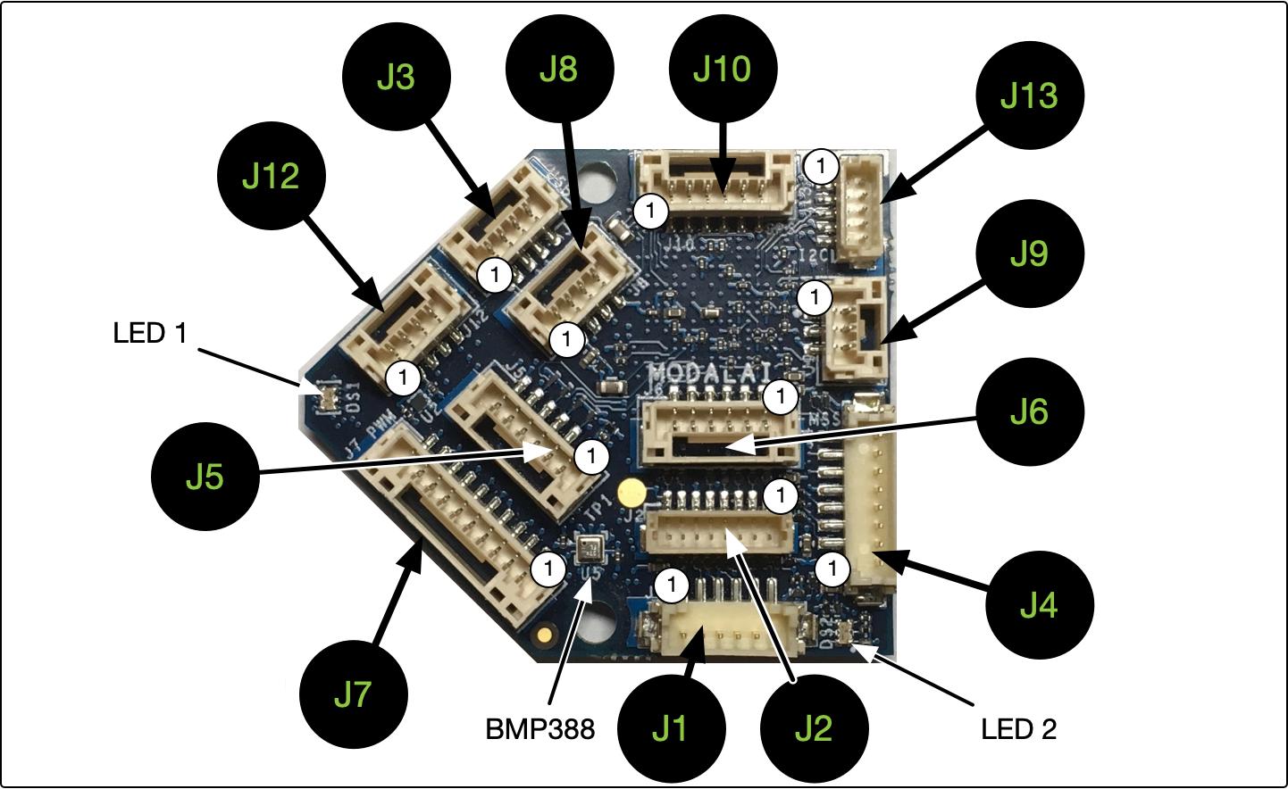
For detailed pinout descriptions see FlightCore Pinout
Dimensions
Block Diagram
UART Mapping
The UARTs are marked Rn and Tn in the above pinouts. The Rn pin is the receive pin for UARTn. The Tn pin is the transmit pin for UARTn.
- SERIAL0 -> USB
- SERIAL1 -> UART7 (Telem1)
- SERIAL2 -> UART5 (Telem2)
- SERIAL3 -> USART1 (GPS)
- SERIAL4 -> UART4 (GPS2)
- SERIAL5 -> USART2
- SERIAL6 -> USART6 (spektrum RCIN)
- SERIAL7 -> USART3
- SERIAL8 -> USB2
RC Input
RC input is configured on both the PPM input pin and the "spektrum" USART6 UART. The PPM pin supports all one-way RC protocols. For protocols requiring half-duplex serial to transmit telemetry (such as FPort) you should use the spektrum port, mapped to SERIAL6. Both PPM and spektrum ports are enabled for RCIN by default.
PWM Output
The ModalAI_v1 supports up to 8 PWM outputs on the PWM output connector
The PWM is in 2 groups:
- PWM 1, 2, 3, 4 in group1
- PWM 5, 6, 7, 8 in group2
Channels within the same group need to use the same output rate. If any channel in a group uses DShot then all channels in the group need to use DShot.
Power Monitoring
In addition to the normal range of ArduPilot power monitoring options, the modalAI build supports two I2C power monitors, the INA231 and the LTC2946. The FlightCore board comes with the INA231 and you should set BATTERY_MONITOR to 21. For the LTC2946 based power brick you should set BATTERY_MONITOR to 22.
Compass
The ModalAI_v1 does not have a built-in compass, but you can attach an external compass


